Progressive cavity pumps are widely used in various industries for their ability to handle viscous fluids and achieve a steady flow. Understanding the diagrams associated with these pumps is crucial for effective operation and maintenance. This article will help you grasp the essential elements of progressive cavity pump diagrams.
What is a Progressive Cavity Pump?
A progressive cavity pump consists of a helical rotor and a stator, which work together to move fluids through the pump. The rotor’s rotation creates a series of cavities that transport the fluid without pulsation. This unique design makes it suitable for handling slurries, sludge, and other challenging materials.
Key Components of a Progressive Cavity Pump Diagram
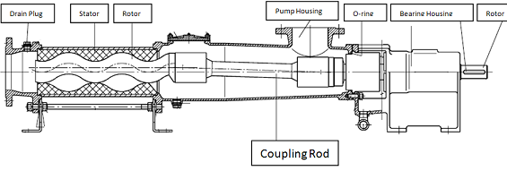
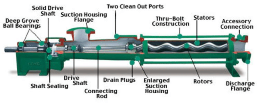
To comprehend a progressive cavity pump diagram, it is important to identify its key components. Here are the main parts you will typically see in the diagram:
- Rotor: The helical component that rotates and creates the cavities.
- Stator: The stationary part that encases the rotor and forms the cavities with it.
- Suction Side: The inlet where the fluid enters the pump.
- Discharge Side: The outlet where the fluid exits the pump.
- Drive Shaft: The mechanism that connects the motor to the rotor.
- Bearing Housing: Provides support and alignment for the rotor and drive shaft.
- Seals: Prevent leakage of the fluid and protect the internal components.
Analyzing the Diagram
When looking at a progressive cavity pump diagram, consider the following steps for a better understanding:
- Identify the Flow Direction: Arrows in the diagram typically indicate the direction of fluid flow. Understanding this direction is essential for correct installation and operation.
- Recognize Component Relationships: Look for how the rotor and stator interact. The diagram should illustrate how the rotor fits inside the stator and forms the cavities essential for pumping.
- Examine the Labels: Diagrams often include labels for each component. Familiarize yourself with these labels to better understand the function of each part.
- Review the Operational Sequence: Some diagrams might depict the operational sequence of the pump. This sequence illustrates how the rotor’s movement generates pressure and facilitates fluid movement.
Common Applications of Progressive Cavity Pumps
Progressive cavity pumps are used in various industries due to their versatility. Here are some common applications:
- Food and Beverage: For handling viscous materials like sauces and pastes.
- Wastewater Treatment: To pump sludge and other thick fluids.
- Oil and Gas: For transferring crude oil and other hydrocarbons.
- Chemical Processing: To manage various industrial chemicals and slurries.
Conclusion
Understanding progressive cavity pump diagrams is vital for anyone involved in the operation or maintenance of these pumps. By familiarizing yourself with the key components, analyzing the diagram, and recognizing the pump’s applications, you can enhance your knowledge and efficiency in working with progressive cavity pumps. Whether you are a technician, engineer, or operator, mastering these diagrams will contribute to better performance and reliability of these essential devices.